How important is calibration for a peel test & lap shear strength tester for photovoltaic (pv) modules, and how is it done?
Introduction: The bedrock of reliable data
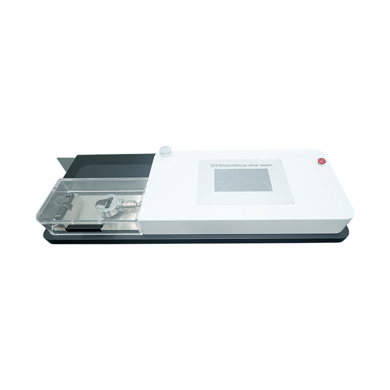
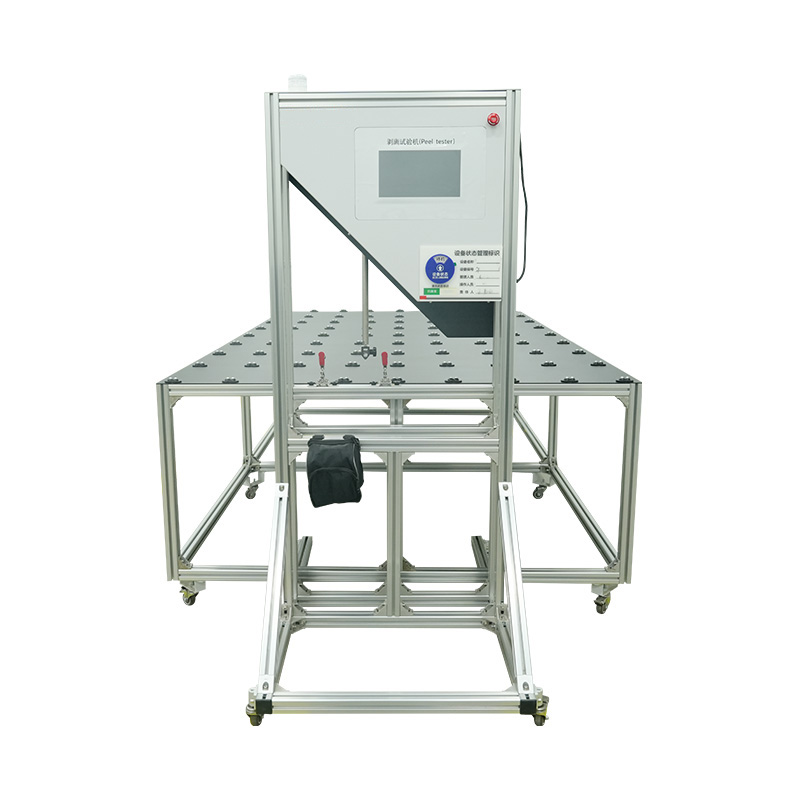
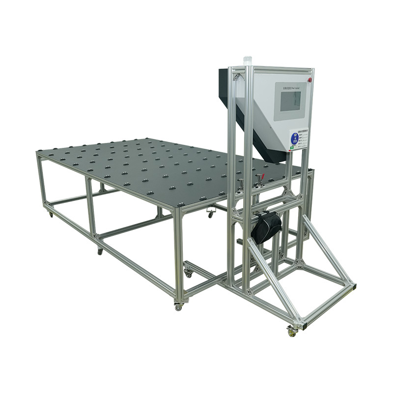
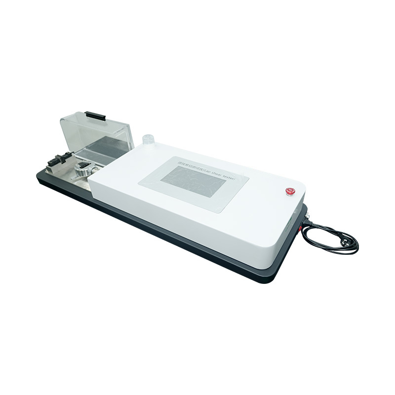
In the precise world of photovoltaic module manufacturing, quality assurance is not merely a step in the process; it is the fundamental guarantee of product performance, longevity, and safety. At the heart of this assurance for encapsulation integrity lies the peel test & lap shear strength tester for photovoltaic (pv) modules. This sophisticated instrument is tasked with quantitatively measuring the adhesive strength between critical layers—such as the glass, ethylene-vinyl acetate (EVA) or polyolefin elastomer (poe) encapsulant, solar cells, and backsheet. These measurements are vital, as they directly correlate to the module’s ability to resist delamination, a primary failure mode that can lead to power loss, moisture ingress, and ultimately, catastrophic failure. However, the data generated by this tester is only as trustworthy as the calibration process that underpins it. Without regular and meticulous calibration, the most advanced peel test & lap shear strength tester for photovoltaic (pv) modules becomes little more than an expensive piece of metal, producing numbers of questionable validity that can compromise an entire production batch or r&d project.
The critical role of calibration: More than just a routine check
Calibration is the act of comparing the measurements of an instrument against a known reference standard to quantify and eliminate any errors in its accuracy. For a peel test & lap shear strength tester for photovoltaic (pv) modules, this is not a mere administrative formality but a technical imperative. The importance of this process can be broken down into several key areas.
First and foremost, calibration ensures data integrity and traceability. The results from these testers, such as a 180-degree peel strength value or a lap shear strength in newtons per square millimeter, are used to validate whether materials meet stringent international standards like iec 61215, iec 61730-2 (mst 35 and mst 36), and iec 62788-1-4. These standards define the minimum acceptable adhesion levels required for a module to be certified as reliable for long-term field deployment. Inaccurate data could lead to the acceptance of substandard modules, risking premature failure in the field, or the rejection of perfectly good modules, resulting in unnecessary financial loss. Precise calibration provides the traceability链 needed to prove that every data point can be trusted and is linked to national or international measurement standards.
Secondly, calibration is essential for process control and quality improvement. In a manufacturing environment, consistent adhesion strength is a key performance indicator. Slight drifts in a tester’s load cell or displacement sensor can mask true trends in the production process. For instance, a gradual decrease in measured peel strength might be misinterpreted as a problem with the EVA lamination process, when in fact, the tester itself is drifting out of specification. Regular calibration isolates the performance of the testing equipment from the performance of the materials, allowing engineers to make accurate, data-driven decisions to optimize lamination parameters like temperature, pressure, and vacuum time.
Furthermore, calibration upholds compliance and certification. Auditors and certification bodies require documented evidence that all testing equipment is maintained and calibrated on a regular schedule. A robust calibration program, often requiring accreditation to standards like ISO/iec 17025, is a non-negotiable aspect of operating a certified photovoltaic module testing laboratory. Without it, the entire validity of the test reports can be called into question, potentially voiding product certifications.
Finally, calibration protects investment and reduces risk. A peel test & lap shear strength tester for photovoltaic (pv) modules is a significant capital investment. Proper calibration maintains its accuracy and reliability over time, safeguarding that investment. More importantly, it mitigates the enormous financial and reputational risk associated with shipping products that May fail in the field due to undetected encapsulation flaws. It is a proactive measure that is vastly more cost-effective than dealing with warranty claims and recalls.
The calibration process: A systematic approach
The calibration of a peel test & lap shear strength tester for photovoltaic (pv) modules is a detailed procedure that should be performed by trained technicians, often using accredited calibration services. The process typically involves verifying the accuracy of two primary systems: The force measurement system and the displacement or speed control system.
1. Pre-calibration preparation
Before any measurements are taken, a visual inspection of the equipment is conducted. This includes checking for any physical damage to the load frame, grips, and fixtures. The grips used for peel tests (often roller grips) and lap shear tests (typically wedge or pneumatic grips) must be inspected for wear and alignment, as misaligned grips can introduce significant bending moments and errors into the measurement. The tester should be installed in a controlled environment, free from vibrations and significant temperature fluctuations, as per the manufacturer’s specifications.
2. Force measurement system calibration
The heart of the tester is its force transducer, or load cell. The calibration of this system is paramount.
- Reference standards: the calibration is performed using calibration grade reference load cells or dead weights that are themselves traceable to national standards (e.G., nist in the united states or nim in China). Dead weights are typically used for lower force ranges and provide the highest possible accuracy for verifications.
- Procedure: the reference standard is connected in series with the tester’s own load cell. The machine is then commanded to apply a force in tension (and sometimes compression, if applicable) through a series of increasing and decreasing points across the entire force range of the instrument. For example, measurements might be taken at 10%, 20%, 50%, 80%, and 100% of the instrument’s capacity.
- Data analysis: at each force point, the reading from the reference standard is compared to the reading from the tester’s system. The error is calculated, and parameters like repeatability, precision, and hysteresis are evaluated. The goal is to ensure that the force measurement error is within the tolerances specified by the manufacturer and the relevant testing standards, often within ±0.5% or better of the indicated value.
3. Displacement and speed system calibration
The rate at which a test is performed is critical for obtaining comparable results, as adhesion strength can be rate-sensitive.
- Reference standards: this calibration is performed using a calibrated displacement transducer or a laser interferometer.
- Procedure: the reference transducer is set up to measure the actual crosshead displacement. The machine’s crosshead is then moved at various specified speeds (e.G., 50 mm/min, 100 mm/min, 200 mm/min) over a known distance.
- Data analysis: the displacement and speed values reported by the testing machine are compared to the values measured by the reference standard. The accuracy of the crosshead position and the consistency of the speed are verified to be within acceptable limits, typically a small percentage of the set value.
4. Software and data acquisition verification
Modern testers are controlled by sophisticated software. Calibration also involves verifying that the software is correctly acquiring, processing, and reporting the data from the sensors. This May involve inputting known electrical signals into the data acquisition system to simulate sensor outputs and confirming that the software interprets them correctly.
5. Documentation and certification
Upon successful completion of the calibration, a calibration certificate is issued. This document is a crucial record. It details the procedures followed, the standards used, the environmental conditions, the as-found data (if it was out of tolerance before adjustment), and the as-left data (after adjustment). It will also state the measurement uncertainty for the calibration process itself. Any adjustments made to bring the equipment into specification are recorded. This certificate provides the necessary proof of traceability and compliance for auditors and customers.
A typical calibration summary might be presented as follows:
| Calibration component |
reference standard used |
key parameters verified |
typical acceptable tolerance |
| Force measurement |
dead weights / reference load cell |
accuracy, repeatability, hysteresis |
±0.5% of reading or better |
| Displacement/speed |
laser interferometer / calibrated encoder |
speed accuracy, position accuracy |
±0.5% of set value or better |
| Grip alignment |
visual and mechanical inspection |
parallelism, absence of play |
within manufacturer’s specification |
Implementing a calibration program: Frequency and service
Establishing a routine calibration schedule is essential. The frequency of calibration depends on several factors: The frequency of use of the tester, the criticality of the measurements, the stability of the equipment, and the requirements of quality standards. A common practice is an annual calibration cycle. However, if the equipment is used heavily or in a critical quality control environment, a semi-annual schedule might be warranted. Additionally, many facilities perform intermediate checks using daily or weekly control samples or simpler verification devices to ensure the equipment remains in a state of control between full calibrations.
Companies can choose between two main service options: in-house calibration or third-party accredited calibration service. In-house calibration requires a significant investment in reference standards, trained personnel, and an established quality system to maintain traceability. For most manufacturers and laboratories, employing an accredited external calibration service provider is the most efficient and reliable method. These providers send mobile laboratories to the site or require the instrument to be shipped to their facility, ensuring the calibration is performed to the highest accredited standards.
The calibration of a peel test & lap shear strength tester for photovoltaic (pv) modules is a fundamental pillar of quality assurance in the photovoltaic industry. It transcends a simple maintenance task, serving as the critical link that ensures the reliability, accuracy, and traceability of the data used to judge the durability of solar modules. Without it, the trustworthiness of test results vanishes, jeopardizing product quality, regulatory compliance, and ultimately, the financial and reputational standing of a manufacturer. By implementing a rigorous and regular calibration program, backed by thorough documentation, companies can have full confidence in their adhesion strength measurements. This confidence empowers them to produce high-quality, reliable photovoltaic modules that will perform as expected for decades in the field, thereby supporting the global transition to sustainable energy with integrity and technological excellence.


 EN
EN
 English
 中文简体
中文简体


 [email protected]
 +86-17712471297