-
 [email protected]
-
 +86-17712471297
[email protected]
+86-17712471297

Content
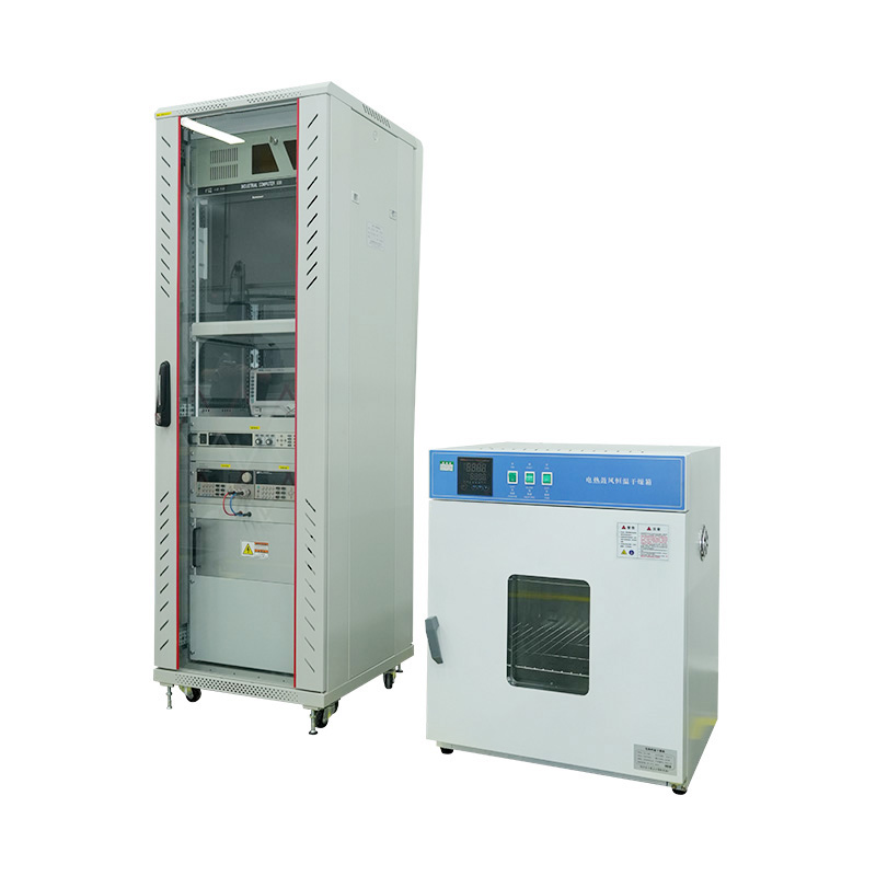
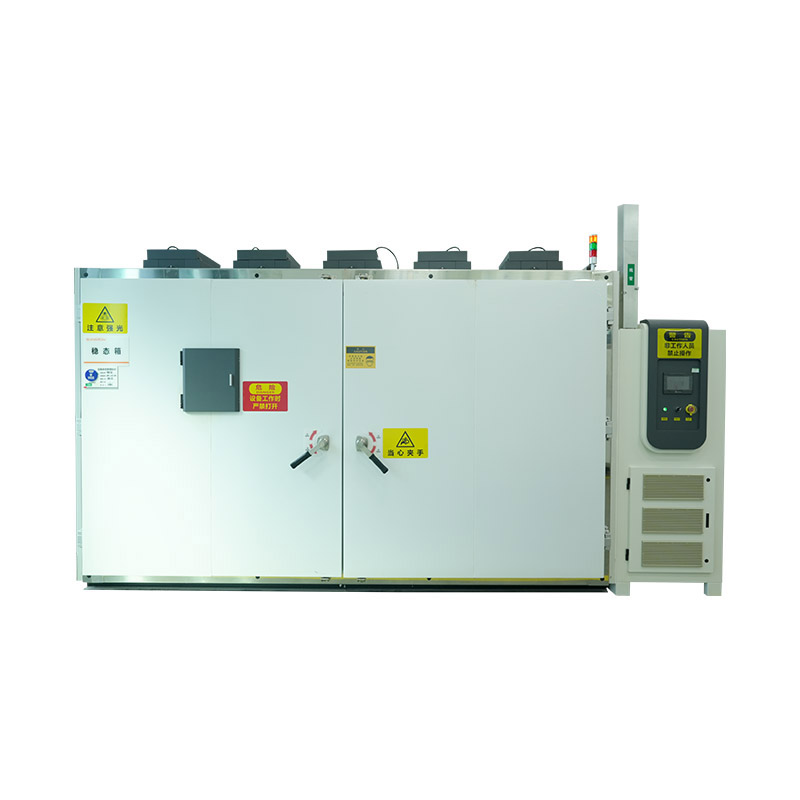
A solar simulation environmental chamber combines an artificial light source that mimics the sun's spectrum with a sealed chamber capable of controlling temperature, humidity, and sometimes altitude or vibration. Instead of waiting months for outdoor field exposure data, engineers can compress years of sun and heat exposure into a controlled test lasting days or weeks.
The two systems have to work together precisely: the light source must deliver a spectrum close to natural sunlight (typically referenced against AM1.5G or AM0 standards), while the chamber maintains the exact temperature and humidity profile the test protocol calls for — without the lamp's own heat output skewing the readings.
Solar simulators are graded on three criteria — spectral match, spatial uniformity, and temporal stability — each rated A, B, or C under IEC 60904-9 and similar standards. A Class AAA simulator scores an A in all three categories.
| Class | Spectral Match Tolerance | Typical Use Case |
|---|---|---|
| Class A | 0.75-1.25x reference spectrum | Precision PV cell testing, R&D labs |
| Class B | 0.6-1.4x reference spectrum | Module-level QC, production testing |
| Class C | 0.4-2.0x reference spectrum | General weathering and material screening |
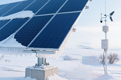
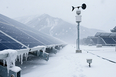
Real-world degradation rarely comes from sunlight alone — it's the combination of heat, moisture, and UV cycling that accelerates material failure. Most test protocols layer several parameters into a single program:
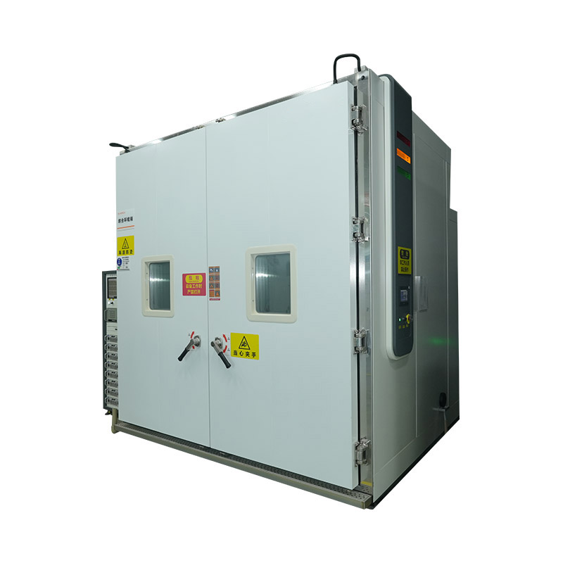
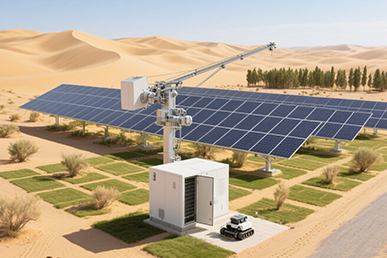
While photovoltaic module qualification is the most common use case, the same chamber architecture serves several other industries:
Chamber size is driven by sample dimensions rather than just throughput. A few sizing considerations matter more than raw internal volume:
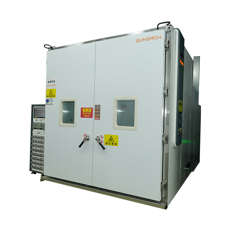
Lamp output degrades over operating hours, so irradiance calibration against a certified reference cell is required on a regular schedule — often every 50-100 operating hours for xenon systems. Skipping calibration is one of the most common causes of inconsistent or non-reproducible test results between labs.
Filter replacement, lamp housing cleaning, and periodic uniformity mapping across the full test plane are equally important. A drifting spectrum or uneven irradiance pattern can quietly invalidate months of accumulated test data before anyone notices the trend.
Because these systems combine precision optics with environmental engineering, manufacturer track record matters more than with standard test equipment. Useful questions to ask before purchasing:


We value your suggestions and questions. If you have any questions about our products and services, please contact us. We will treat you responsibly and reply to your information as soon as possible.
 Building 14, Chuangjin Industrial Park, Zhitang Town, Changshu City, Suzhou City, Jiangsu, China
 +86-17712471297

 EN
EN