-
 [email protected]
-
 +86-17712471297
[email protected]
+86-17712471297

Content
Damp heat testing subjects electronic assemblies, materials, and finished products to sustained conditions of elevated temperature and high relative humidity in order to assess their resistance to moisture-induced degradation. It is one of the most widely specified environmental qualification tests in global electronics, photovoltaics, aerospace, and automotive standards — because combined heat and humidity is one of the most destructive real-world environments a product can face.
Moisture accelerates virtually every failure mechanism relevant to electronic and electromechanical products: metal corrosion, insulation resistance loss, delamination of composite laminates, swelling of polymer encapsulants, electrochemical migration between conductors, and hydrolysis of adhesive bonds. At elevated temperatures, the diffusion rate of water vapor through seals, coatings, and encapsulants increases dramatically — conditions at 85°C and 85% RH drive moisture ingress roughly ten to twenty times faster than ambient laboratory conditions, enabling accelerated lifetime prediction within practical test durations.
The damp heat test category encompasses several distinct test protocols — steady-state damp heat, the 85/85 endurance test, solar climatic testing, and humidity freeze cycling — each targeting different failure modes and applicable to different product categories. Understanding the differences between these protocols is essential for selecting the right test for a qualification program.

IEC 60068-2-78 is the primary international standard governing steady-state damp heat testing for components and equipment. It defines test method Cab — a fixed-condition soak at a specified temperature and relative humidity for a defined duration — and is referenced by product standards across telecommunications, industrial electronics, consumer goods, and renewable energy equipment.
The standard defines a set of preferred test severities. The most commonly applied conditions are:
Standard test durations under IEC 60068-2-78 are defined in preferred steps: 4, 10, 21, 56, 96, 160, 504, 672, 1000, and 2000 hours. The 1000-hour duration at 85°C/85% RH has become a de facto benchmark for photovoltaic module qualification under IEC 61215, while 96 or 168 hours at 40°C/93% RH is typical for general component screening.
Damp heat storage testing evaluates the effect of humid conditions on a non-powered, non-operating specimen — simulating warehouse storage, shipping in humid climates, or seasonal dormancy. The product is placed in the chamber unpowered and assessed after exposure for changes in electrical parameters, mechanical dimensions, insulation resistance, and cosmetic condition. This is the most common application of IEC 60068-2-78 in component qualification programs.
Damp heat operation testing — sometimes called damp heat endurance — runs the specimen powered and functional during the entire exposure period. This is a significantly more demanding condition, as joule heating from the operating circuit creates thermal gradients that drive moisture deeper into the assembly, and electrochemical migration failures are accelerated by the combination of live voltage, high humidity, and elevated temperature. Product standards for medical devices (IEC 60601), industrial controls (IEC 61010), and outdoor power electronics typically require operational damp heat testing in addition to storage testing.
The 85/85 test — named for its conditions of 85°C temperature and 85% relative humidity — is the most widely recognized accelerated humidity endurance test in the electronics industry. It originated in semiconductor reliability testing during the 1970s as a means of assessing the moisture resistance of plastic-encapsulated integrated circuit packages, and has since been adopted across photovoltaics, printed circuit board assemblies, display modules, LED luminaires, and battery systems.
The physical rationale for these specific conditions is that 85°C/85% RH represents the practical upper boundary of conditions achievable reliably in standard chamber designs while remaining below the glass transition temperature of most standard epoxy encapsulants and PCB laminates. More severe conditions (e.g., 85°C/95% RH or 110°C/85% RH) are used in highly accelerated stress testing (HAST) for advanced semiconductor packages, but require specialized pressure-vessel chambers rather than standard damp heat equipment.
The photovoltaic industry has adopted the 85/85 test as a cornerstone of module durability qualification under IEC 61215 (crystalline silicon modules) and IEC 61646 (thin-film modules). The standard specifies 1000 hours at 85°C / 85% RH as a pass/fail qualification test, with acceptance criteria including a maximum 5% degradation in maximum power output, no major visual defects (delamination, bubble formation, discoloration), and no insulation resistance failure.
For bifacial modules and high-efficiency cell architectures, extended 85/85 durations of 2000 hours are increasingly specified by project developers and insurance underwriters as part of enhanced durability qualification programs — particularly for utility-scale solar installations in high-humidity tropical and coastal environments where damp heat stress is a primary long-term degradation driver.
For semiconductor packages, the 85/85 test is specified in JEDEC standard JESD22-A101 and is used to assess moisture-induced failures including delamination between mold compound and die paddle, corrosion of aluminum bond wires, and parametric drift in sensitive analog circuits. Test durations of 168 hours (one week) to 1000 hours are applied depending on the qualification level — consumer, industrial, or automotive grade.
For assembled PCBs and finished electronic modules, the 85/85 test identifies failures including electrochemical migration (dendrite growth between conductors), flux residue activation under humidity, degradation of conformal coating adhesion, and failure of press-fit or crimped connector interfaces. Testing is typically conducted with the assembly powered at nominal voltage to maximize electrochemical driving force during the test.
Solar climatic testing combines simulated solar irradiance with controlled temperature and humidity to replicate the most aggressive real-world outdoor exposure condition — direct sunlight on a product surface in a hot, humid climate. This is qualitatively different from standard damp heat testing: ultraviolet radiation photochemically degrades polymer materials (encapsulants, backsheets, potting compounds, housing plastics) at a rate far exceeding what heat and humidity alone would produce, and the combination of UV exposure and high humidity simultaneously attacks both the surface chemistry and the bulk moisture resistance of the specimen.
Solar climatic test chambers are equipped with xenon arc lamp arrays or UV fluorescent lamp banks calibrated to a defined irradiance spectrum (typically matching the global solar spectrum per ISO 9845-1 for xenon, or the UV-A/UV-B bands for fluorescent lamp systems) alongside the temperature and humidity control systems of a conventional damp heat chamber. The combined stress profile allows qualification of products for outdoor deployment without conducting multi-year field exposure trials.
For outdoor luminaires, traffic control equipment, and building-integrated photovoltaics, solar climatic testing sequences that combine UV exposure, damp heat soaks, and thermal shock cycles provide the most realistic assessment of long-term field performance. Sequential multi-stress programs are increasingly favored over single-stressor tests in advanced qualification standards, as synergistic damage mechanisms between UV, heat, and moisture produce failure modes not observable in any single-condition test alone.
Humidity freeze testing — also called damp cold or freeze-thaw humidity cycling — subjects specimens to repeated transitions between high-humidity warm conditions and sub-zero cold conditions. The critical failure mechanism targeted is freeze-thaw damage to moisture that has already been absorbed into the specimen: water that diffuses into polymer encapsulants, composite laminates, or porous substrates during the humid warm phase expands by approximately 9% upon freezing, generating internal stresses that crack encapsulants, delaminate interfaces, and fracture brittle materials such as solder joints and ceramic components.
This failure mechanism is distinct from those targeted by thermal shock testing (which uses dry air or liquid media and targets coefficient-of-thermal-expansion mismatch) and from standard damp heat testing (which does not include a freeze phase). Humidity freeze testing is therefore an independent qualification requirement for products deployed in climates with cold winters and humid summers — northern European, Canadian, Korean, and Japanese climates are the primary environments driving this requirement.
IEC 60068-2-30 defines Damp Heat Cyclic test method Db, which cycles between a high-humidity warm phase (typically 40°C / 93–97% RH) and a low-temperature phase (typically +25°C or lower), with controlled ramp rates designed to produce surface condensation on the specimen during the warm-to-cold transition. This condensation phase — where liquid water forms on and within the specimen — is itself a distinct and damaging condition beyond the bulk humidity of the warm soak.
For photovoltaic modules, IEC 61215 includes a humidity freeze test sequence consisting of a damp heat pre-conditioning soak at 85°C/85% RH followed by thermal cycling to −40°C — specifically designed to assess whether moisture absorbed during the damp heat phase causes mechanical damage when subsequently frozen. This combined sequence has identified failures in module encapsulants and junction box potting compounds that neither test alone would reveal.
Cumulative cycle counts of 10, 20, or 50 cycles are the most commonly specified durations, depending on the product standard and deployment environment severity. Failure criteria typically include insulation resistance below a defined threshold, power output degradation exceeding 5% (for PV modules), cracking visible under 10× magnification, and delamination detectable by electroluminescence imaging.
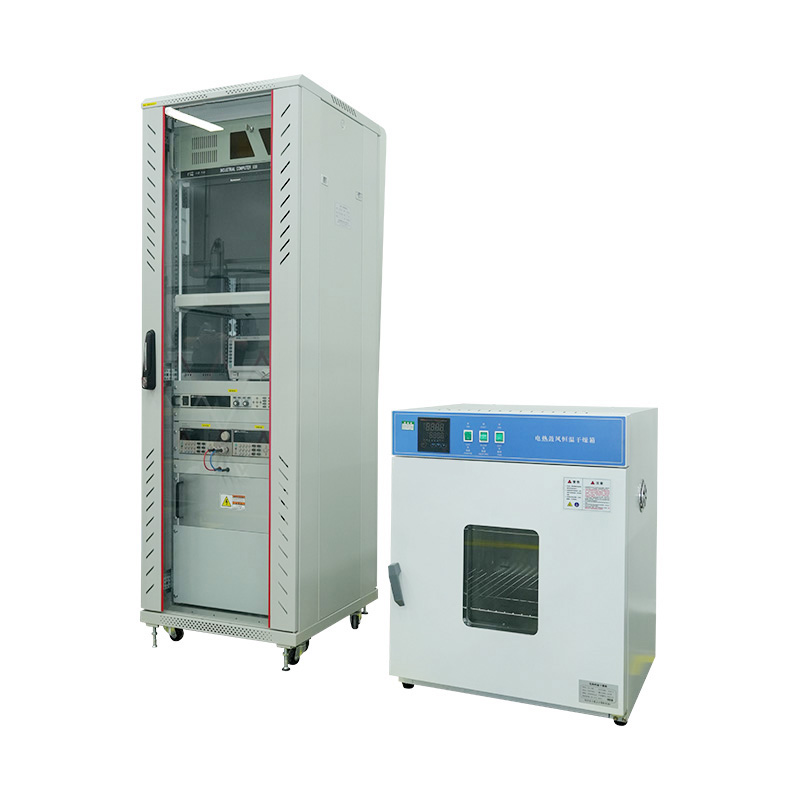
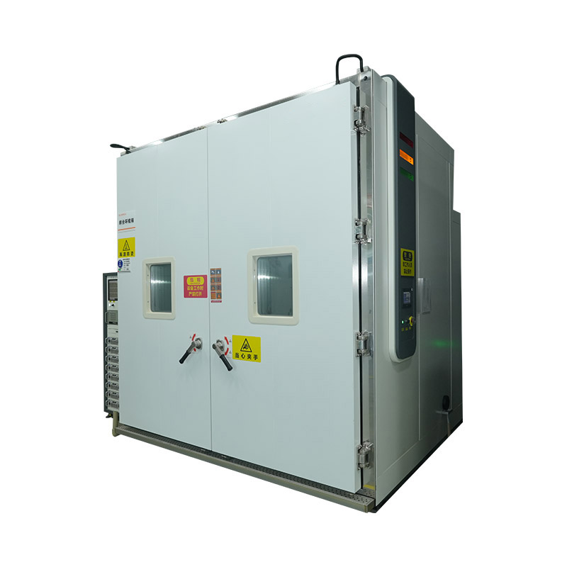
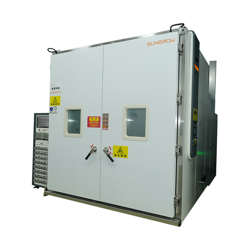
A damp heat test chamber must maintain precise, stable, and uniform temperature and humidity conditions throughout the test volume for the entire test duration — which may extend to 2000 hours or more for demanding qualification programs. Chamber performance directly determines test validity: a chamber that cannot hold 85°C ±2°C and 85% RH ±2% RH simultaneously at the specimen surface is not capable of producing a defensible 85/85 test result.
| Test Type | Standard | Conditions | Duration | Primary Application |
|---|---|---|---|---|
| Damp Heat Steady State | IEC 60068-2-78 | 40°C/93% RH; 40°C/85% RH; 55°C/93% RH | 96–1000 h | General electronics, storage qualification |
| 85/85 Test | IEC 60068-2-78 / IEC 61215 / JESD22-A101 | 85°C / 85% RH | 1000–2000 h | PV modules, semiconductors, PCB assemblies |
| Damp Heat Cyclic | IEC 60068-2-30 | 40°C/93% RH ↔ +25°C cycles | 6, 12, 21 cycles | Connectors, enclosures, condensation resistance |
| Humidity Freeze | IEC 61215 (PV) / IEC 60068-2-30 | 85°C/85% RH → −40°C freeze cycles | 10–50 cycles | PV modules, outdoor enclosures, cold-climate products |
| Solar Climatic | IEC 60068-2-5 / ISO 4892 | UV irradiance + elevated T + humidity | Per standard sequence | Outdoor equipment, PV, polymer materials |
Matching the test protocol to the product's intended deployment environment and the applicable product standard is the starting point for any damp heat qualification program. The following framework covers the most common decision points:


We value your suggestions and questions. If you have any questions about our products and services, please contact us. We will treat you responsibly and reply to your information as soon as possible.
 Building 14, Chuangjin Industrial Park, Zhitang Town, Changshu City, Suzhou City, Jiangsu, China
 +86-17712471297

 EN
EN