I. Overview: What Are PV Module Testing Chambers?
A PV module testing chamber is a specialized piece of equipment used to simulate harsh environmental conditions to evaluate the performance, reliability, and long-term durability of photovoltaic (PV) modules. They are a critical tool for quality control and product development in the solar industry.
Definition and Core Objectives
- Definition: A PV module testing chamber precisely controls internal environmental parameters such as temperature, humidity, UV radiation, and salt mist concentration to replicate various climate conditions a module might face in real-world applications. Its primary purpose is to simulate years of outdoor exposure, often 20-25 years or more, in a condensed laboratory setting.
- Core Objectives:
- Quality Verification: To ensure the manufacturing quality of modules meets design requirements and industry standards.
- Performance Evaluation: To monitor changes in key parameters like power output and insulation performance under environmental stress, assessing their degradation rate.
- Reliability Certification: To provide the necessary test data and evidence for modules to obtain international certifications like IEC and UL.
- New Materials/Technologies R&D: To quickly validate the long-term reliability impact of new materials and encapsulation technologies through accelerated aging tests.
Core Functionality Comparison and Parameter Listing
The following table lists the core functionalities of different types of testing chambers and their common parameter ranges for a better understanding of their professional use.
| Chamber Type |
Simulated Environmental Stress |
Core Functionality |
Common Parameter Range |
| Damp Heat Chamber |
High temperature and humidity |
Evaluates the resistance of encapsulation materials, backsheets, and junction boxes to heat and moisture, identifying issues like delamination and electrode corrosion. |
Temperature: +85℃; Relative Humidity: 85%; Duration: 1000 hours |
| Thermal Cycling Chamber |
Drastic temperature changes |
Assesses mechanical stress on modules from thermal expansion and contraction, identifying issues like solder joint cracks, cell microcracks, and delamination. |
Temperature Range: -40℃ to +85℃; Cycles: 200 or more; Cycle Period: Several hours per cycle |
| UV Chamber |
Solar UV radiation |
Evaluates the anti-aging properties of module encapsulation materials (e.g., EVA, backsheet) against UV radiation, preventing yellowing and embrittlement. |
Irradiation Intensity: approx. 15 kWh/㎡ (340nm band), higher than outdoor levels; Test Duration: typically 60kWh/㎡ or more |
| Hail Impact Tester |
Hailstone impact |
Evaluates the mechanical impact resistance of the module's glass cover and frame, ensuring physical integrity in severe weather. |
Impact Energy: Simulated with plastic or special material ice balls of different masses and velocities, e.g., 25mm, 35mm, 45mm diameters |
| Salt Mist Corrosion Chamber |
High-salinity environment |
Evaluates the corrosion resistance of module frames, brackets, junction boxes, and internal cell components in marine or coastal environments. |
Salt Mist Concentration: 5% NaCl solution; Temperature: +35℃; Duration: 480 hours or more |
By precisely simulating single or combined environmental stresses, these chambers help solar industry professionals gain deep insights into potential module failure modes, enabling continuous improvements in product design and manufacturing processes to ultimately deliver more reliable and efficient solar products to users.
II. Main Types and Classification
PV module testing chambers can be meticulously classified into various types based on their testing purpose and application scenarios. Each type addresses a specific environmental stress a module might encounter in actual use. Understanding these classifications is crucial for selecting the appropriate testing equipment and designing effective test plans.
1. Classification by Test Purpose
This classification is based on the primary environmental stress simulated by the chamber and is the most common method in the industry.
- Thermal Cycling Chambers:
- Core Functionality: Simulates dramatic temperature fluctuations caused by day-night cycles, seasonal changes, or extreme weather events.
- Working Principle: By rapidly switching between low and high temperatures, the chamber induces repeated mechanical stress on the materials inside the module. This stress primarily affects solder joints, cells, and the interface of lamination materials.
- Purpose: To evaluate the mechanical integrity of the module, particularly to identify fatigue cracks or microcracks in solder joints, interconnects, and cells.
- Damp Heat Chambers:
- Core Functionality: Simulates high-temperature and high-humidity climates found in tropical or humid regions.
- Working Principle: The chamber maintains constant high temperature and humidity, accelerating the penetration of water vapor into the module.
- Purpose: To evaluate the moisture resistance of module encapsulation materials (like EVA, backsheets) and prevent corrosion, short circuits, or power degradation caused by moisture intrusion on internal metal components.
- UV Chambers:
- Core Functionality: Simulates the UV portion of the solar spectrum, which is highly destructive to materials.
- Working Principle: Special light sources (such as xenon lamps) are used to simulate solar UV light, with precise control over its intensity and duration.
- Purpose: To evaluate the anti-aging properties of module encapsulation materials, preventing yellowing, embrittlement, or performance degradation from long-term exposure.
- Hail Impact Testers:
- Core Functionality: Simulates the mechanical impact of hailstones during extreme weather events.
- Working Principle: A pneumatic or spring-loaded device launches plastic or special material ice balls of specific mass and diameter at high speed to impact the module's glass cover.
- Purpose: To verify the structural integrity and glass resistance to physical impact, ensuring the module can withstand severe weather.
- Salt Mist Corrosion Chambers:
- Core Functionality: Simulates high-salinity environments in coastal areas or near oceans.
- Working Principle: A saline mist containing sodium chloride (NaCl) is sprayed inside the chamber to create a highly corrosive environment.
- Purpose: To evaluate the corrosion resistance of the module's frame, brackets, junction box, and internal components under salt mist conditions, which is especially critical for offshore solar farms and coastal projects.
2. Classification by Scale and Application
This classification focuses more on the practical use and installation location of the testing equipment.
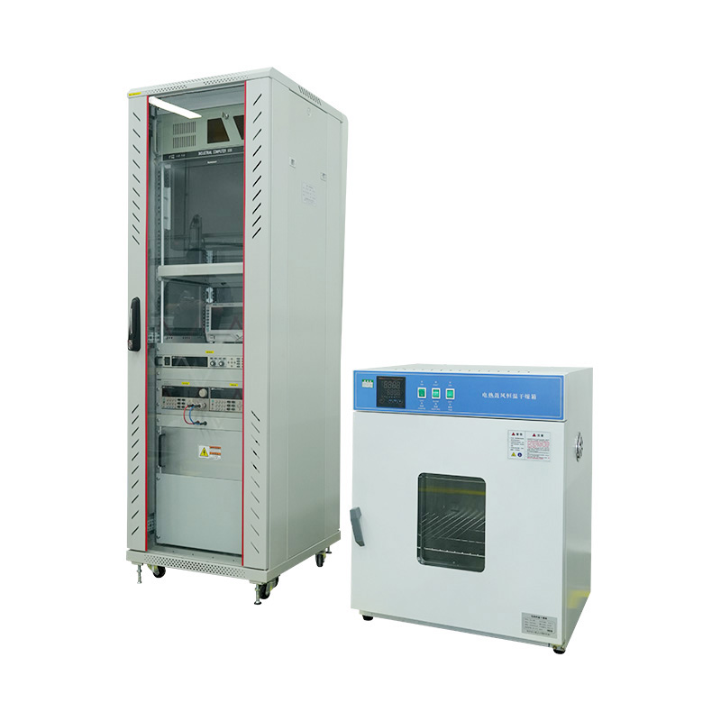
- Laboratory-Grade Chambers:
- Features: Generally smaller, testing a limited number of modules at a time, but with comprehensive functions and high precision.
- Application Scenarios: Primarily used in R&D centers, university labs, or during new product development by module manufacturers to verify the reliability of new materials and technologies.
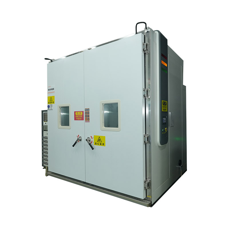
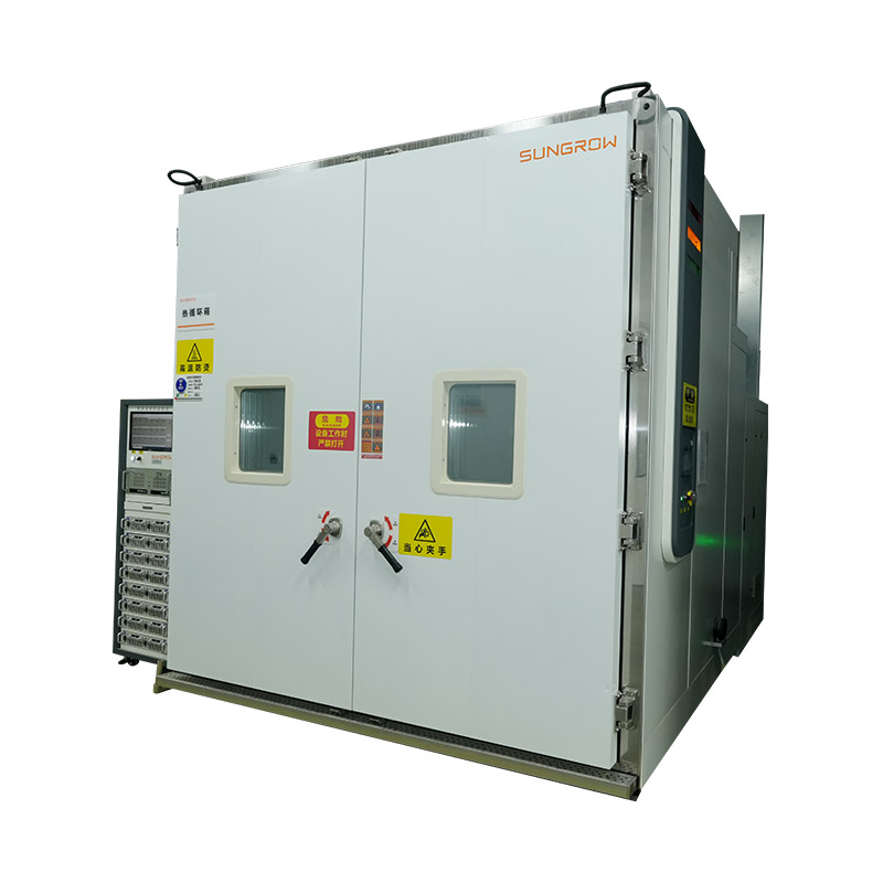
- Production-Line Grade Chambers:
- Features: Larger in size, designed to test multiple modules simultaneously or integrated into automated production lines for fast, continuous quality sampling.
- Application Scenarios: Mainly used in PV module manufacturing plants as part of the quality control (QC) process, performing random sampling to ensure consistent quality of finished products.
These different types of testing chambers form the cornerstone of the PV module quality assurance system. They work together to verify the long-term reliability and performance stability of PV modules in various complex environments.
III. Core Testing Standards and Methods
To ensure that test results from different PV module testing chambers are comparable and universally applicable, a series of strict international standards and testing methods have been established. These standards not only define the performance requirements for the chambers but also specify detailed test procedures and evaluation metrics, serving as the foundation for product certification in the solar industry.
1. IEC Standards: The Global Industry Norms
The International Electrotechnical Commission (IEC) is the most authoritative organization for setting PV module testing standards. Its published standards are adopted globally for product design qualification and type approval.
- IEC 61215: Design Qualification and Type Approval for Terrestrial Crystalline Silicon PV Modules:
- Core Content: This is the most fundamental and important standard for crystalline silicon PV modules. It defines a series of rigorous test sequences to simulate the long-term performance and reliability of modules under normal outdoor conditions.
- Tests Covered: Includes key tests like Thermal Cycling (TC), Damp Heat (DH), UV preconditioning, and Humidity-Freeze (HF).
- Purpose: To verify that the module's design is robust and can withstand the long-term challenges of outdoor environments.
- IEC 61730: Photovoltaic Module Safety Qualification:
- Core Content: This standard focuses on the electrical and mechanical safety of modules, ensuring they do not pose a danger to users during operation.
- Tests Covered: Includes insulation tests, fire tests, and terminal strength tests.
- Purpose: To guarantee the electrical isolation, fire rating, and mechanical integrity of the module under various stresses, preventing risks like electric shock and fire.
- IEC 62716: Photovoltaic Modules - Ammonia Corrosion Testing:
- Core Content: This is a standard for specific applications (e.g., farms, landfills) where high concentrations of ammonia gas can corrode module encapsulation materials and metal parts.
- Test Method: Modules are placed in a special chamber with ammonia gas and exposed under high temperature and high humidity conditions.
2. Key Testing Procedures and Evaluation Methods
Regardless of the standard, module testing follows a strict procedure, with key parameters compared before and after testing to quantify the impact of environmental stress on the module.
- Pre-Test Preparation:
- Visual Inspection: Records any visual defects on the module surface, such as scratches, bubbles, or delamination.
- Initial Performance Measurement: Under Standard Test Conditions (STC), the module's maximum power (Pmax), open-circuit voltage (Voc), short-circuit current (Isc), and fill factor (FF) are precisely measured. These values serve as the baseline for comparison.
- Testing Phase:
- Chamber Operation: The module is placed in the corresponding chamber and run according to the specified temperature, humidity, number of cycles, or exposure time.
- Parameter Monitoring: Some advanced chambers monitor the module's electrical performance in real-time to detect any immediate failures during the test.
- Performance Evaluation and Parameter Comparison:
- Post-Test Measurement: After all tests are completed, the module's electrical performance, especially the maximum power (Pmax), is measured again under STC.
- Degradation Rate Calculation: This is the most important evaluation metric. The power degradation rate is calculated by comparing the post-test power ($P_{final}$) with the initial power ($P_{initial}$).
Power Degradation = $\frac{P_{initial} - P_{final}}{P_{initial}} \times 100\%$
Key Test Parameter Comparison
The table below compares the parameters of several core tests in the IEC 61215 standard to highlight their stringency:
| Test Name |
IEC 61215 Standard Parameters |
Main Evaluation Effect |
Allowed Power Degradation Rate |
| Thermal Cycling (TC 200) |
200 cycles, -40℃ to +85℃ |
Simulates day-night temperature changes, evaluates fatigue stress on solder joints and interconnects. |
$\leq 5\%$ |
| Damp Heat (DH 1000) |
+85℃, 85% RH, 1000 hours |
Simulates high temp/humidity, evaluates moisture penetration and material corrosion. |
$\leq 5\%$ |
| UV Preconditioning (UV Precon) |
Total UV irradiation $\geq 15$ kWh/㎡ |
Simulates UV aging, evaluates yellowing and embrittlement of encapsulation materials. |
$\leq 5\%$ (evaluated in conjunction with other tests) |
Note: The final power degradation rate is typically a comprehensive calculation after completing all test series (e.g., TC, DH, HF). Only when the power degradation rate after all tests meets the standard's requirements is the module considered to have passed type qualification. These strict standards and clear test methods are crucial for ensuring that PV modules can operate stably and reliably in complex outdoor environments.
IV. Key Technologies and Design Considerations
The professionalism and reliability of PV module testing chambers lie not only in their ability to simulate various environments but also in the precision technologies and user-friendly designs they incorporate. These core technologies ensure the accuracy and repeatability of test results while safeguarding the operator and the equipment itself.
1. Temperature and Humidity Control System
This is the core of all environmental testing chambers, and its performance directly determines the validity of the test results.
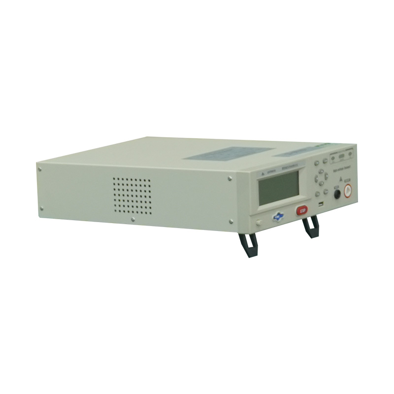
- High-Precision Sensors: Use high-precision temperature sensors like platinum resistance (Pt100) and capacitive humidity sensors to ensure real-time and accurate monitoring of internal parameters.
- Rapid Response: Employ PID (Proportional-Integral-Derivative) control algorithms combined with efficient refrigeration/heating elements, allowing the chamber to quickly reach and stabilize at the set temperature and humidity, which is especially critical for thermal cycling tests.
- Uniformity: A forced air circulation system ensures that temperature and humidity are highly uniform throughout the chamber, preventing test result deviations due to local temperature differences.
2. Irradiation Simulation System
For tests requiring sunlight simulation (like UV tests), the performance of the irradiation system is key.
- Light Source Selection: Typically uses xenon arc lamps or UV fluorescent tubes. Xenon arc lamps have a spectrum closer to sunlight, while fluorescent tubes are more economical and have a longer lifespan.
- Spectral Match: Professional testing chambers' light sources must be spectrally corrected to ensure their irradiation intensity in key wavelength bands (e.g., 340nm, 420nm) matches sunlight, accurately simulating the material aging process.
- Irradiation Intensity Control: Through photosensors and dimming systems, the output of the light source is monitored and adjusted in real-time to maintain a constant irradiation intensity throughout the test.
3. Safety Protection and Data Acquisition
To ensure the safety of equipment and operators and to record complete test data, these functions are essential.
- Multiple Safety Interlocks: Including over-temperature protection, over-voltage protection, leakage protection, and door interlocks. The equipment automatically cuts power and sounds an alarm when any abnormal situation occurs.
- Data Logging and Monitoring: The chamber is typically equipped with a data logger or computer system to record temperature, humidity, irradiation intensity, and the module's current, voltage, and other electrical parameters in real-time. This data can be exported for analysis, providing a detailed basis for fault diagnosis and performance evaluation.
4. Scalability and Customization
- Modular Design: Some high-end chambers feature a modular design, allowing for the addition of different testing functionalities as needed, such as PID and HF tests.
- Customized Dimensions: Given the variety of PV module sizes, chambers can be customized to fit specific module dimensions, maximizing space utilization and testing efficiency.
Key Technical Parameter Comparison
The table below compares the design considerations for key technical parameters across different testing chambers:
| Technical Type |
Thermal Cycling Chamber |
Damp Heat Chamber |
UV Chamber |
| Temperature Control |
Rapid ramp rate (usually > 10℃/min), wide temperature range |
Constant temperature control, high precision (usually ±1℃) |
Constant temperature, typically between 40-60℃ |
| Humidity Control |
Not a critical parameter, usually no precise humidity control |
Constant humidity control, high precision (usually ±3%RH) |
Usually no humidity control, or added for specific test modes |
| Light Source |
None |
None |
Xenon arc or UV fluorescent lamp, high spectral match requirement |
| Data Acquisition |
Focuses on recording temperature changes, cycle count, and module power degradation |
Records temperature, humidity, and module power degradation |
Records irradiation dose, intensity, and module power degradation |
These precise control systems and thoughtful design considerations ensure that PV module testing chambers provide credible and reliable test data for the solar industry, driving continuous technological progress and product quality improvement.
V. Market Applications and Industry Trends
PV module testing chambers are more than just laboratory tools; they are an indispensable part of the solar value chain. Their widespread application and continuous evolution reflect the industry's relentless pursuit of product quality and reliability.
1. Market Application Fields
PV module testing chambers are used throughout a product's lifecycle, and their user base is very broad.
- Product R&D: During the design and new material development phases, R&D personnel use testing chambers for accelerated aging tests on new materials, encapsulation technologies, and cell types. This helps them quickly validate the reliability of new technologies and shorten product development cycles. For example, when developing a new backsheet material, it will immediately undergo UV and damp heat tests to predict its long-term weatherability.
- Production Quality Control (QC): PV module manufacturers install testing chambers on their production lines for random sampling. Thermal cycling and damp heat tests can quickly identify potential defects like poor soldering or lamination bubbles, ensuring the consistent quality of finished products.
- Third-Party Certification and Testing Institutions: These independent bodies (e.g., TÜV, UL, CQC) are the cornerstone of industry trust. They use high-standard testing chambers to perform type qualification and certification for PV modules according to international standards. Modules must pass these rigorous tests to get a "pass" to be sold on the market.
- Solar Project Developers: Before constructing large-scale solar farms, project developers or investors commission third-party institutions to test candidate modules to evaluate their performance and reliability in the project's climate, thereby reducing investment risk.
2. Industry Development Trends
With the rapid iteration of solar technology and the expanding global market, PV module testing chamber technology and applications are continuously evolving, showing the following key trends:
- Stricter Testing Standards: To cope with extreme climates and ever-increasing module power, new IEC standards are being developed or updated. For example, the number of thermal cycles is increasing from 200 to 600 or more to better simulate long-term fatigue stress on modules in the field. This requires chambers to have higher temperature change rates and longer operational stability.
- Integration and Intelligence of Testing Equipment: Future chambers will be more than single-function devices; they will be integrated platforms with multiple testing capabilities (e.g., PID, LID, LeTID). Smart features like remote monitoring, automated data analysis, and fault diagnosis will become standard, greatly improving testing efficiency and data management.
- Focus on Emerging Failure Modes: As module technology advances, new failure modes (e.g., PID effect, LID effect, and snail trails) are gaining attention. Corresponding chambers are being upgraded to simulate these specific environmental stresses and evaluate the module's resistance. This drives the development of more specialized and specific testing chamber technologies.
- Diversification of Test Objects: In addition to traditional crystalline silicon modules, emerging thin-film, perovskite, and other solar technologies also require customized testing solutions. This prompts chamber manufacturers to develop equipment that can accommodate the unique characteristics of different materials and structures, adapting to the industry's diverse development direction.
Test Standard Parameter Comparison (Example: Thermal Cycling)
The table below compares the parameters of the Thermal Cycling (TC) test in different versions of the IEC 61215 standard, which clearly shows the industry's move towards more rigorous testing:
| Standard Version |
Number of Cycles |
Temperature Range |
Key Change |
| IEC 61215:2005 |
200 cycles |
-40℃ to +85℃ |
Basic test standard, now superseded. |
| IEC 61215:2016 |
200 cycles (basic), 600 cycles (optional) |
-40℃ to +85℃ |
Introduced additional high-intensity tests to meet stricter market demands. |
| Future Trend |
800 cycles or more |
Wider temperature range, higher ramp rates |
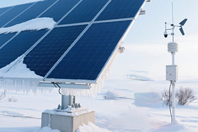
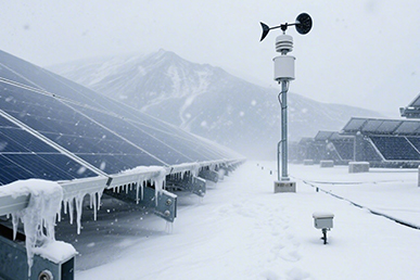
Aimed at more realistically simulating extreme climates, such as deserts or high-altitude regions. |
VI. Conclusion: The Importance of Testing Chambers and Future Outlook
PV module testing chambers play an indispensable role in the solar industry. They are the cornerstone for ensuring the quality, reliability, and long-term performance of solar products. Their existence allows the entire lifecycle of a PV module—from lab design to large-scale commercial application—to be scientifically and rigorously validated.
1. The Fundamental Importance of Testing Chambers
- Ensuring Product Quality: By using accelerated aging, chambers help manufacturers identify potential material defects, process issues, and design weaknesses before products leave the factory. This guarantees product quality at the source, reducing module failure-related project failures and financial losses.
- Mitigating Project Risk: For solar farm investors, module reliability is directly tied to long-term project revenue. Rigorous testing allows for the selection of high-quality and reliable products, thereby reducing maintenance costs and power output loss risks during plant operation.
- Driving Technological Innovation: Testing chambers provide a rapid validation platform for new materials and technologies. Engineers can simulate years of outdoor exposure in just weeks or months, quickly iterating product designs and accelerating the pace of innovation.
2. Future Outlook
The technology of PV module testing chambers will closely follow the development trends of the entire solar industry, with the future showing the following directions:
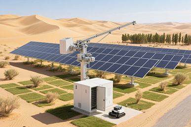
- Diversification of Test Scenarios: As solar applications expand (e.g., floating solar farms, agri-photovoltaics, building-integrated PV), chambers will need to simulate more diverse environments, such as high temp/high humidity, high salt mist, and even combined marine climates.
- Intelligence and Automation: Future chambers will be more intelligent. They will integrate more advanced data acquisition and analysis systems, capable of automatically diagnosing module failure modes and generating detailed test reports. Automated loading and unloading systems will also increase testing efficiency to meet the demands of mass production lines.
- Integration with New Technologies: Chambers will evolve in tandem with increasing module power and the application of new materials (like perovskites) to accommodate higher test power and more precise test requirements. New testing methods will continue to emerge to address new failure issues, such as PID (Potential-Induced Degradation) and LID (Light-Induced Degradation).
Ultimately, PV module testing chambers will be more than just simple environmental simulators; they will become a crucial bridge connecting R&D, manufacturing, and application, continuously safeguarding the healthy and sustainable development of the solar industry.
 [email protected]
 +86-17712471297


 Building 14, Chuangjin Industrial Park, Zhitang Town, Changshu City, Suzhou City, Jiangsu, China
 +86-17712471297

 EN
EN