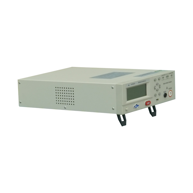
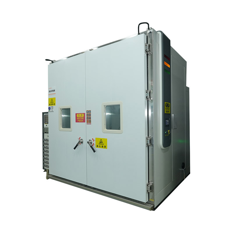
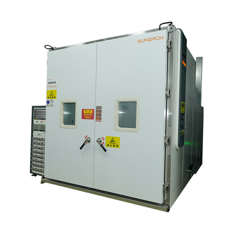
-
 [email protected]
-
 +86-17712471297
[email protected]
+86-17712471297

Content
A PV module testing chamber is a precision climate-control enclosure designed to simulate the full range of environmental stresses that solar panels encounter over their rated service life—typically 25 to 30 years of outdoor exposure. By compressing decades of real-world degradation into controlled laboratory cycles, these chambers allow manufacturers, certification bodies, and research institutions to identify failure modes before modules enter the field.
Environmental durability testing equipment for photovoltaics must satisfy a more demanding set of performance requirements than standard industrial climate chambers. PV modules combine dissimilar materials—tempered glass, encapsulants, cell metallization, backsheets, and junction boxes—each with different thermal expansion coefficients and moisture absorption behaviors. Accelerated aging tests must simultaneously stress all material interfaces to produce failure data that correlates reliably with field degradation rates.
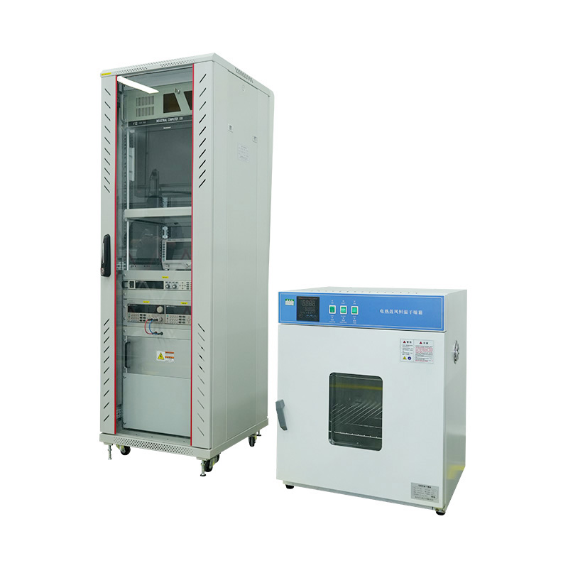
The international qualification standards for crystalline silicon and thin-film PV modules define the specific environmental sequences that testing chambers must replicate. Compliance with these standards is a prerequisite for market access in most major solar markets.
Beyond baseline qualification, extended stress testing protocols such as IEC TS 62804 (potential-induced degradation) and IEC TS 63126 (high-temperature testing for modules rated above 70°C) are increasingly required by utility-scale project developers and financing institutions conducting independent technical due diligence.
A complete PV module qualification laboratory typically requires several distinct chamber types, each optimized for a specific class of environmental stress.
| Chamber / Equipment Type | Primary Test | Key Operating Parameters | Applicable Standard |
|---|---|---|---|
| Thermal cycling chamber | TC200 thermal cycling | −40°C to +85°C, ≥100°C/hr ramp | IEC 61215 |
| Damp heat chamber | DH1000 humidity endurance | 85°C / 85% RH, ±2% RH control | IEC 61215 |
| Humidity freeze chamber | HF10 humidity freeze cycling | −40°C to +85°C with RH control | IEC 61215 |
| UV aging chamber | UV preconditioning | 15 kWh/m² UV dose, 60°C chamber temp | IEC 61215 / IEC 61730 |
| Salt mist / salt fog chamber | Corrosion resistance | 5% NaCl, 35°C, 96–168 hrs continuous | IEC 61701 |
| PID test system | Potential-induced degradation | 85°C / 85% RH + high DC voltage bias | IEC TS 62804 |
Advanced PV testing laboratories increasingly specify electrically biased thermal cycling chambers, which apply a controlled current or voltage to the module under test throughout the temperature cycle. Operating modules at Isc or Voc during thermal excursions stresses cell interconnects, solder joints, and bypass diodes under conditions that more closely replicate real field operation than unbiased cycling. These systems require integrated power supply busbars, feed-through connectors rated for the chamber's full humidity range, and data acquisition channels capable of logging module IV characteristics at each temperature plateau.
Selecting a PV module testing chamber requires evaluating specifications that go beyond the temperature and humidity ranges stated on a product datasheet. The following parameters have the greatest influence on test accuracy, throughput, and long-term operating cost:
Procurement of PV module testing chambers represents a significant capital investment—individual chambers range from USD 30,000 for basic damp heat units to over USD 300,000 for large-format multi-stress systems. Due diligence at the sourcing stage substantially reduces the risk of acquiring equipment that cannot support accreditation or produces non-correlating test data.
Requesting a witnessed factory acceptance test at the manufacturer's facility—where the chamber is run through a complete IEC 61215 thermal cycle and damp heat sequence with calibrated reference sensors—remains the most reliable method of verifying that delivered equipment will meet the performance specifications required for accredited PV module qualification testing.



We value your suggestions and questions. If you have any questions about our products and services, please contact us. We will treat you responsibly and reply to your information as soon as possible.
 Building 14, Chuangjin Industrial Park, Zhitang Town, Changshu City, Suzhou City, Jiangsu, China
 +86-17712471297


 EN
EN
 English
 中文简体
中文简体