-
 [email protected]
-
 +86-17712471297
[email protected]
+86-17712471297

Content
A solar panel that appears physically intact can still underperform or fail silently. The most reliable way to confirm a panel is working is to compare its actual output — measured in watts or as an open-circuit voltage reading — against its rated specifications under known irradiance conditions. But several simpler checks can identify problems before any test equipment is connected.
Start with a close examination of the panel surface and frame. Common visual indicators of a failing or underperforming panel include:
For grid-tied systems, the inverter display or monitoring app is the first data point. A functioning panel array will show DC input voltage and current within the inverter's operating window. Most modern string inverters and microinverters log daily and cumulative energy production; a sudden drop in kWh generation relative to a clear-day baseline is the clearest early indicator of a panel fault. Compare today's output against the same day in previous months using the monitoring platform's historical data. A well-oriented panel in full sun should produce approximately 250–400 Wh per rated watt per year depending on location, tilt, and shading.
When a visual check and monitoring data point to a specific panel, direct electrical measurement is the definitive diagnostic. The two key parameters are open-circuit voltage (Voc) and short-circuit current (Isc), both listed on the panel's datasheet. Testing should be performed in full, unobstructed sunlight — ideally at solar noon — and results compared against datasheet values at Standard Test Conditions (STC: 1000 W/m² irradiance, 25°C cell temperature). A panel measuring significantly below its rated Voc (more than 5–10%) or Isc warrants further investigation.
A multimeter is the standard tool for solar panel field testing, but several practical methods allow meaningful performance assessment without one.
Connect the panel to a device with a known power requirement — a DC LED light, a small fan, or a USB charge controller with a display. If the device operates at expected brightness or speed under direct sunlight, the panel is producing usable voltage and current. This method does not yield precise measurements but confirms basic functionality. A panel that fails to operate a load it should easily power (based on rated wattage vs load wattage) has a significant problem.
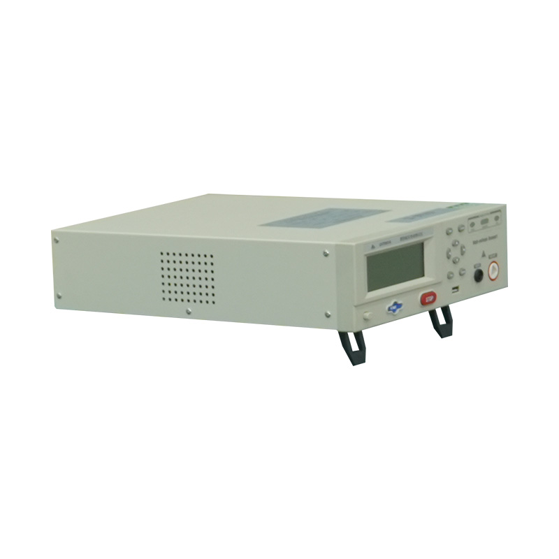
A DC clamp meter measures current without breaking the circuit — simply clamp around one conductor in the panel output cable. This gives Isc (approximately) in full sun and can be compared against the datasheet value. Dedicated solar panel analyzers (also called I-V curve tracers) go further: they sweep the panel's operating range and plot the full current-voltage curve, identifying not just whether the panel is producing current but whether its maximum power point (Pmax) and fill factor are within acceptable limits. These tools are increasingly affordable for field service teams, with entry-level models available from $150–$500.
An infrared (IR) camera reveals temperature anomalies across the panel surface without any electrical contact. Hotspots — cells or cell clusters running significantly hotter than surrounding areas — indicate bypass diode failure, cell cracking, or internal delamination. Thermal imaging is now standard practice in large-scale PV plant maintenance: a drone-mounted IR camera can survey an entire utility installation in a single pass, flagging panels that require ground-level inspection. Handheld IR cameras suitable for residential system checks start around $300–$800.
EL imaging applies a forward current through the panel and captures the light emitted by the silicon cells using a near-infrared camera. Healthy cells emit uniformly; cracked, degraded, or disconnected regions appear as dark areas. EL imaging detects microcracks and cell-level defects invisible to the naked eye and undetectable by voltage or current measurement alone. This technique is primarily used in manufacturing quality control and large-scale plant diagnostics rather than residential field service, but it is the most sensitive non-destructive test available for crystalline silicon modules.
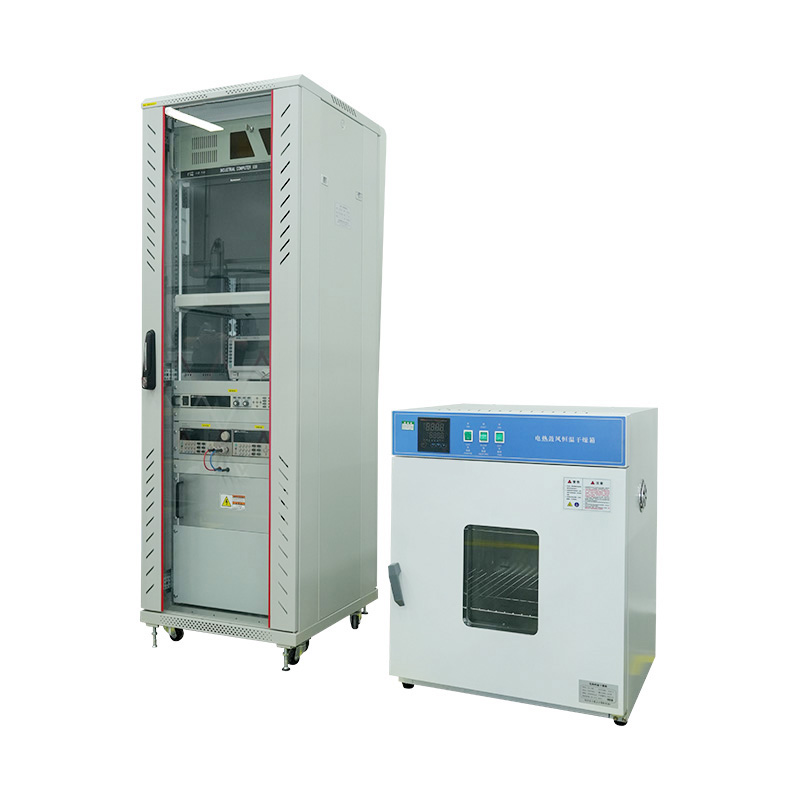
Solar module testing equipment ranges from handheld field instruments to precision laboratory systems used to certify panels against international standards. Understanding the purpose of each category helps buyers and test engineers select the right tool for the job.
| Equipment Type | Key Parameters Measured | Use Context | Approximate Cost |
|---|---|---|---|
| Digital Multimeter | Voc, Isc (approximate) | Field diagnostics, residential service | $20–$200 |
| I-V Curve Tracer | Full I-V curve, Pmax, Vmp, Imp, fill factor | Commercial plant commissioning, O&M | $500–$8,000 |
| Solar Simulator (Flash Tester) | STC-corrected I-V curve, Pmax, efficiency | Manufacturing QC, laboratory certification | $20,000–$500,000+ |
| Infrared Camera | Cell temperature distribution, hotspots | Field inspection, plant maintenance | $300–$10,000+ |
| EL Imaging System | Cell crack mapping, internal defects | Manufacturing QC, incoming inspection | $5,000–$80,000 |
| Environmental Test Chamber | Performance under temperature/humidity stress | Reliability testing, IEC 61215 certification | $15,000–$200,000+ |

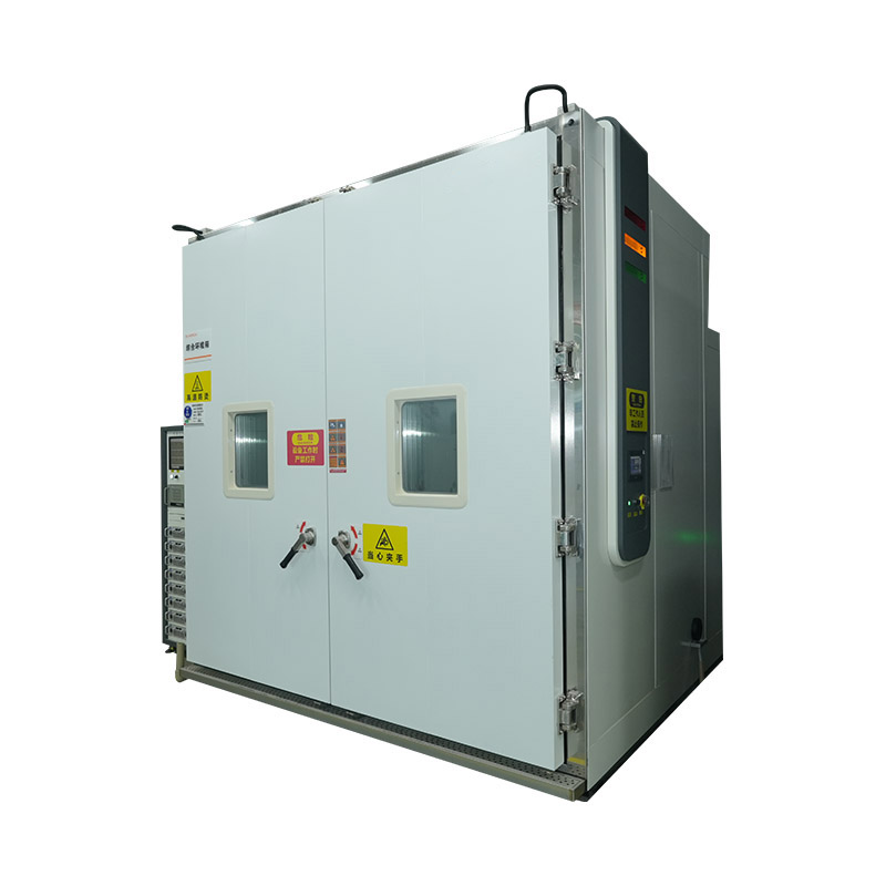
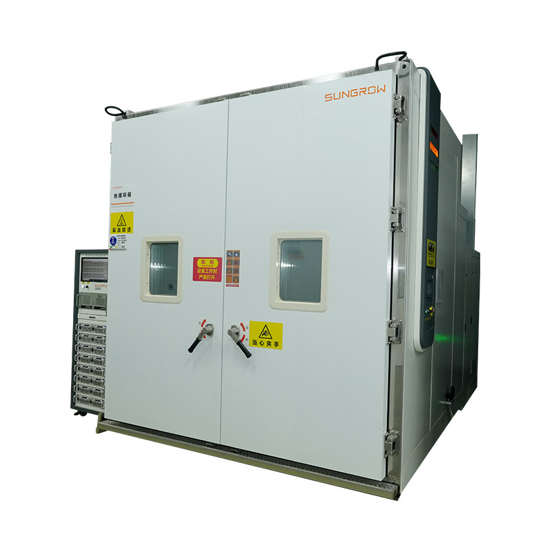
Solar panel testing chambers are environmental simulation systems used to verify that photovoltaic modules meet the durability and performance requirements of international standards — primarily IEC 61215 (crystalline silicon modules) and IEC 61730 (safety qualification). These tests are mandatory for module certification by accredited bodies such as TÜV, UL, and Bureau Veritas, and are required by most national incentive programs and grid connection regulations.
Testing chambers used for solar module qualification must meet specific performance requirements that differ from standard environmental chambers used in electronics or materials testing. Critical specifications include:
Manufacturers and third-party certification laboratories investing in solar panel testing capabilities typically source chambers specifically configured for IEC 61215 compliance rather than repurposing general-purpose environmental test equipment, as the dimensional, electrical, and humidity performance requirements are more demanding than most standard chamber specifications.


We value your suggestions and questions. If you have any questions about our products and services, please contact us. We will treat you responsibly and reply to your information as soon as possible.
 Building 14, Chuangjin Industrial Park, Zhitang Town, Changshu City, Suzhou City, Jiangsu, China
 +86-17712471297

 EN
EN