-
 [email protected]
-
 +86-17712471297
[email protected]
+86-17712471297

Testing for potential-induced degradation (PID) and hot spots in photovoltaic modules requires a combination of standardized laboratory procedures and field detection techniques. PID testing follows IEC TS 62804-1, which defines three test methods: dark environment tests for PID-shunting and ultraviolet light tests for PID-polarization. A typical accelerated PID test subjects modules to 85 degrees Celsius, 85 percent relative humidity, and 1000 volts for 96 hours, with post-test power degradation exceeding 5 percent considered a failure. Hot spot detection relies primarily on infrared thermography — field data from a 24.9 MWp system in Sumatra showed hotspot formation as the dominant defect, causing excessive localized heating and material degradation. This article provides a practical, step-by-step framework for both laboratory-based quality assurance and field-level troubleshooting.

Content
Potential-induced degradation (PID) is a performance deterioration mechanism that occurs when high voltage stress between the solar cells and the grounded module frame drives leakage currents through the glass, encapsulant, and cell structure. Sodium ions from the glass migrate into the silicon solar cells, creating short circuits that reduce efficiency. PID particularly affects modules operating in damp environments with high system voltages, where the degradation can cause performance losses and permanent output reductions within months of installation. Without proper testing, modules susceptible to PID can experience power losses exceeding 30 percent within the first year of operation, increasing the levelized cost of energy (LCOE) by 15 to 20 percent. Testing for PID susceptibility is therefore not optional—it is a fundamental quality assurance requirement for module manufacturers and a critical due diligence step for project developers and asset owners.
The latest IEC TS 62804-1:2025 defines procedures to evaluate the durability of crystalline silicon photovoltaic modules to short-term high-voltage stress, primarily PID. The standard provides three test methods organized into two types. The first type, conducted in the dark with two variations, is primarily designed for assessing PID-shunting—the mechanism where sodium ions cause localized short circuits in the cell. The second type, which also has two variations, incorporates ultraviolet light and is intended for assessing PID-polarization, where mobile ions influence the electric field over the silicon semiconductor or electronically interact with it. A separate test for the recovery of PID polarization under ultraviolet light is also included. The standard is designed for crystalline silicon PV modules with passivating dielectric layers and can be used for guidance on thin-film, tandem, or heterojunction devices.
The standard laboratory method for PID testing follows a well-defined protocol that accelerates the degradation mechanism under controlled conditions. The test sequence typically includes the following steps.
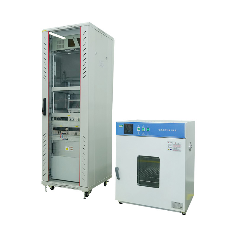
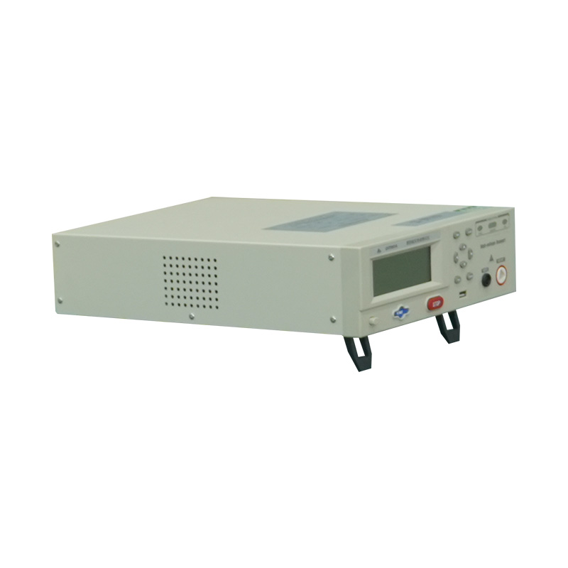
Dedicated PID test systems are purpose-built to perform the high-voltage stress testing required by IEC TS 62804-1. These systems integrate a high-voltage power supply, multi-channel monitoring, environmental chamber interface, and safety protections into a single platform. A typical system such as the SST-PV-PID provides 8 to 12 independent output channels, enabling simultaneous testing of multiple modules. Each channel delivers an adjustable voltage up to plus or minus 1500 volts, with real-time current display and leakage current monitoring across all channels simultaneously. Key specifications of a professional PID test system include voltage accuracy of plus or minus 0.5 percent full scale, current measurement resolution of 0.001 milliamps, and an integrated industrial computer with software for automated data logging, curve display, and configurable test duration settings.
The system connects the module's internal conductors to one terminal of the high-voltage supply and the module frame to the other. Positive and negative polarity can be switched via software without changing physical connections, enabling both PID stress testing and recovery testing. Critical safety features include over-current alarms that force the output to zero when any channel exceeds 1 milliamp, over-voltage protection, and communication interfaces with the environmental chamber that automatically shut down the power supply if the chamber fails. For manufacturers, systems like the PIDcon from Freiberg Instruments allow testing at the solar cell and mini-module level, enabling quality control earlier in the production chain and evaluation of encapsulation materials before full module assembly.
While laboratory testing is essential for certification, modules already installed in the field require a different approach. The PIDcheck portable device, developed by the Fraunhofer Center for Silicon Photovoltaics (CSP) and Freiberg Instruments, enables on-site PID testing without removing modules from the solar array. This mobile device simulates the conditions under which PID occurs—elevated temperatures and a high electrical potential between the glass surface and solar cell—and completes a measurement within four to eight hours, compared to the minimum 96 hours required for standard laboratory testing. The device creates an electrical contact between the module surface and a conductive electrode, exposing approximately half of the cells to PID stress. Even if no PID has been previously detected in the system, the PIDcheck can determine the installed modules' susceptibility to future degradation. If PID has already occurred, the device can predict future module performance and support reversible high-voltage polarity for on-site PID recovery.
Hot spots are localized areas of abnormal high temperature on photovoltaic modules where individual cells or sections become significantly warmer than surrounding areas. Under normal operation, solar cells maintain relatively uniform temperatures across the panel surface. When a hotspot develops, affected cell temperatures can reach 150 to 200 degrees Celsius, far exceeding normal operating conditions. Data from field studies shows that a single hot spot can cause a module power generation loss exceeding 30 percent, increasing the plant's LCOE by 15 to 20 percent. The most common causes include partial shading, cell mismatch, manufacturing defects, soiling, and electrical resistance problems. Shading alone accounts for 80 percent of hot spot cases in overseas power plants according to NREL's 2022 Module Failure Report. When a cell is shaded while others remain illuminated, the shaded cell stops generating power and instead consumes it, converting electrical energy into heat through reverse bias operation.
Field investigations in real-world installations reveal the severity of this problem. A study of a 24.9 MWp solar PV system in Sumatra, Indonesia, identified hotspot formation as the dominant operational defect, alongside 350 cases of junction box failures and 282 cases of glass cracking primarily linked to hotspots and mechanical impacts. In desert environments such as Qatar, infrared inspection of modules operational since 2014 revealed that 39 percent of modules had hot spots at the location of junction boxes, with additional hot spots found at other locations across the panel surface. Sustained high temperatures cause backsheet yellowing, cell performance degradation, and in extreme cases, can even lead to module self-ignition or fire hazards when temperatures approach the backsheet ignition point around 300 degrees Celsius.
IEC 61215 defines the hot spot endurance test, designed to determine a module's ability to withstand the heating effects that can cause solder melting, encapsulation degradation, and permanent damage. The test sequence consists of four distinct stages.
The first step is to determine which cell experiences the most severe hot spot heating. The standard gives two methods for series-connected and series-parallel modules. The first method involves short-circuiting the module without shading and directly locating the cell with the highest stable operating temperature using thermal imaging. The second method—which is generally recommended—involves short-circuiting the module and sequentially shading each individual cell, then selecting the cell whose shading causes the greatest reduction in short-circuit current. This method is preferred because short-circuit current measurements are more precise and directly relate to the power dissipated by the mismatched cell. The irradiance source must provide at least 700 watts per square meter with non-uniformity not exceeding plus or minus 2 percent.
After identifying the most susceptible cell, the next step determines at what shading percentage the hot spot temperature peaks. Using a set of opaque masks with shading increments of 5 percent, gradually reduce the illuminated area of the target cell while monitoring the stable temperature on the back surface of the shaded region. The shading ratio producing the highest temperature is then used for the endurance test.
With the worst-case cell and shading ratio determined, the module undergoes a 5-hour exposure under a steady-state solar simulator or natural sunlight at an irradiance of 1000 watts per square meter plus or minus 10 percent. Because natural sunlight cannot maintain 10 percent stability over five continuous hours, a steady-state solar simulator is practically required. Xenon lamps approximating the solar spectrum are the preferred choice, with the test plane irradiance non-uniformity kept below plus or minus 10 percent through careful lamp array design and a stabilized power supply.
Following the endurance test, the module undergoes visual inspection for any cracks, bubbles, or delamination. If a serious visual defect is found, the module fails. If minor defects are present, two additional cells are subjected to the same test. The module must also demonstrate that its maximum output power at STC has not degraded by more than 5 percent and that insulation resistance meets the same requirements as the initial test.
In operating solar plants, thermal imaging cameras provide the most effective method for detecting hot spots. Professional infrared inspections can reveal temperature differences across panel surfaces, with hotspots appearing as bright areas on thermal images indicating elevated temperatures compared to surrounding cells. Inspections should be conducted during peak sunlight hours when modules operate at maximum capacity, ensuring that electrical imbalances and resulting hotspots are most apparent.
Drone-based thermal imaging has become the standard for large-scale installations, combining thermal and visual imaging to efficiently scan extensive panel arrays. Modern drone systems achieve hotspot identification accuracy rates of 99.3 percent and can detect micro-crack sizes as small as 3 millimeters. A typical inspection setup includes a 640 by 512 pixel infrared thermal imager with temperature difference accuracy of 0.1 degrees Celsius alongside a 4K visible light camera. The drone captures images that are then analyzed through thermal mapping software to quickly identify and locate hot spots, junction box failures, and other anomalies. Any temperature anomaly exceeding 10 degrees Celsius above neighboring cells warrants immediate investigation. Visual inspection alone can sometimes reveal signs of hotspot damage including discoloration, browning, or bubbling of panel materials, though these signs typically appear only after hotspots have already caused significant damage.
Although both PID and hot spots degrade module performance, their causes, detection methods, and mitigation strategies differ substantially. The table below provides a direct comparison to guide targeted troubleshooting.
| Characteristic | PID (Potential-Induced Degradation) | Hot Spots |
|---|---|---|
| Primary Cause | High voltage stress, ion migration from glass | Shading, cell mismatch, microcracks, soiling |
| Detection Method | EL imaging, I-V curve analysis, PIDcheck | Infrared thermography, visual inspection |
| Temperature Effect | Uniform cell degradation without localized heating | Localized heating up to 150 to 200 degrees C |
| Reversibility | Partially reversible through reverse bias recovery | Usually irreversible once physical damage occurs |
| Primary Mitigation | Anti-PID encapsulants, proper grounding, cell-level process control | Bypass diodes, half-cut cells, regular cleaning |
Effective management of both PID and hot spots requires proactive measures at the design, manufacturing, and operational stages. For PID, the most impactful strategies begin at the cell and module level. Modifying the silver paste composition to reduce aluminum content and reactive components lowers the risk of chemical reactions under humid conditions. Optimizing the firing process to ensure stable, blister-free anti-reflection coatings helps prevent corrosive reactions. Using PID-resistant encapsulants such as polyolefin elastomer (POE) instead of standard EVA, combined with double-glass module construction, significantly reduces moisture ingress pathways. At the system level, proper grounding configurations and selecting inverters with appropriate voltage ratings relative to system size are essential.
For hot spot prevention, the adoption of half-cut cell technology has proven highly effective. Field data shows that half-cut modules outperform full-cell modules in mitigating hotspot risks due to their lower current per cell and enhanced bypass diode configuration. Reducing the number of modules per string further minimizes hotspot severity. Regular maintenance including cleaning schedules to remove bird droppings, dust, and debris—along with vegetation management to prevent shading—can address the 80 percent of hot spot cases caused by external shading. Implementing routine thermal drone inspections allows early detection before hotspots cause permanent damage, while monitoring systems that flag sudden drops in power output from specific strings can serve as an early warning indicator for developing hotspot problems.
A comprehensive quality assurance approach integrates both PID and hot spot testing at multiple points in the product lifecycle. During manufacturing, PIDcon systems test solar cells and mini-modules for PID susceptibility before full module assembly. Completed modules undergo the full IEC TS 62804-1 PID stress test and IEC 61215 hot spot endurance test for design qualification. For large-scale procurement, third-party laboratories should conduct batch sampling using these standardized methods to verify manufacturer claims. At the project level, pre-installation testing with portable PIDcheck devices establishes a baseline susceptibility profile for the selected module type. Post-installation, annual thermal drone surveys combined with EL imaging on a statistical sample of modules provide ongoing condition monitoring. Module manufacturers who adopt this multi-stage testing framework typically reduce field failure rates by 50 to 70 percent compared to those relying solely on factory flash testing, directly protecting both energy yield and long-term asset value.


We value your suggestions and questions. If you have any questions about our products and services, please contact us. We will treat you responsibly and reply to your information as soon as possible.
 Building 14, Chuangjin Industrial Park, Zhitang Town, Changshu City, Suzhou City, Jiangsu, China
 +86-17712471297

 EN
EN