-
 [email protected]
-
 +86-17712471297
[email protected]
+86-17712471297

Content
A PV test chamber is an environmental testing enclosure built to reproduce the temperature, humidity, and cycling stresses that a solar panel will experience over its outdoor service life, compressed into a controlled indoor timeframe. Instead of waiting 20+ years to see how a module holds up in the field, manufacturers place it inside a chamber and run programmed cycles of extreme heat, cold, and moisture to expose weak points in encapsulation, soldering, and backsheet materials within weeks or months.
The term covers a family of equipment rather than one single machine — a photovoltaic test chamber may be built specifically for thermal cycling, humidity-freeze, damp heat, or a combination of these, depending on which certification protocol it's designed to satisfy.
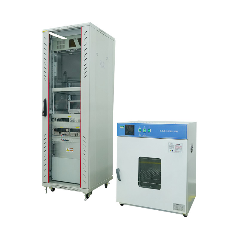
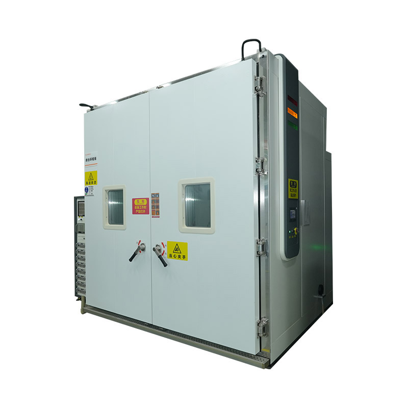
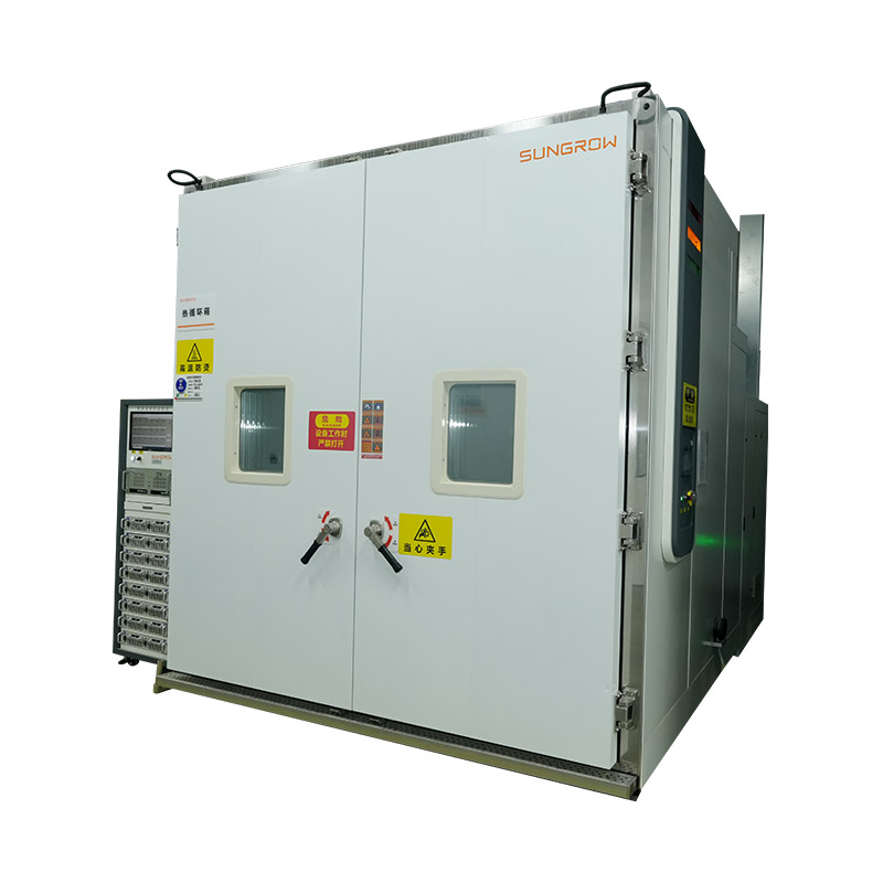
Physically, most chambers are large insulated steel enclosures with a refrigeration and heating system on one side, a humidity generator feeding in through controlled ducting, and a programmable logic controller running the temperature and humidity profile. Panels sit on racks or hang vertically inside the test space, spaced to allow air to circulate evenly across every module surface. Sensors distributed through the interior feed temperature and humidity readings back to the controller in a closed loop, correcting drift in real time so the chamber holds the programmed setpoint rather than just approximating it.
Chamber size is dictated almost entirely by module dimensions. A lab testing residential-scale panels can get away with a smaller footprint, but facilities qualifying utility-scale modules — often 2.3 to 2.5 meters on the long edge — need chambers with correspondingly larger interior volumes, which in turn demands more powerful refrigeration and heating capacity to hit the same ramp rates across a bigger air mass.

Most reliability protocols for solar modules, including IEC 61215 and IEC 61730, rely on a handful of standardized stress tests. Each targets a different failure mechanism:
| Test | Typical Conditions | What It Reveals |
|---|---|---|
| Thermal cycling | -40°C to 85°C, 200–600 cycles | Solder joint fatigue, interconnect cracking |
| Damp heat | 85°C / 85% RH, 1000+ hours | Encapsulant degradation, delamination, corrosion |
| Humidity-freeze | 85% RH down to -40°C, 10 cycles | Combined moisture ingress and thermal stress cracking |
A thermal cycling test chamber for PV modules and a damp heat test chamber for solar panels are sometimes separate pieces of equipment, but many labs now use combined chambers that handle both temperature cycling and humidity control in one enclosure to save floor space and cut equipment cost.
Thermal cycling is generally considered the most mechanically demanding test in the sequence, because it directly attacks the interface between dissimilar materials — solder joints connecting copper ribbon to silicon cells, and the bond between encapsulant and glass. Each cycle expands and contracts these materials at different rates, and after enough repetitions, micro-cracks in solder bonds can grow into open circuits that drop a string's output or, in severe cases, create localized hot spots that shorten the panel's usable life.
Damp heat testing works on a slower timescale but targets a different weakness: moisture ingress through the backsheet or edge seals. Once moisture reaches the encapsulant, it can trigger hydrolysis in EVA-based materials, discoloring the encapsulant and reducing light transmission to the cells, or it can reach the cell surface and accelerate corrosion of the metal grid lines. Because damp heat failures develop gradually, this test typically runs far longer than thermal cycling — 1000 hours is the IEC baseline, though some manufacturers extend it to 2000 hours for bifacial or high-reliability product lines.
Field failures traced back to encapsulant yellowing, backsheet cracking, or solder bond fatigue are almost always catchable in an environmental chamber before a module design ever reaches volume manufacturing. Running new cell technologies, bifacial designs, or new encapsulant formulations through a full IEC test sequence before scaling production is standard practice for module makers trying to avoid warranty claims years down the line — a single design flaw that surfaces after installation is dramatically more expensive to resolve than one caught in pre-production testing.
This is also why PV module reliability testing has become a purchasing criterion for utility-scale buyers, not just a certification checkbox — procurement teams increasingly request extended test data (1.5x or 2x standard cycle counts) beyond the minimum required for IEC compliance.
The economics behind this are straightforward. A gigawatt-scale developer replacing failed modules across a large array faces not just the cost of the replacement panels, but the labor cost of accessing rooftop or ground-mount installations that may already be wired into strings and inverters, plus lost generation revenue during the swap. Extended testing during the design phase is a fraction of that cost, which is why more buyers now treat chamber test reports as a due-diligence document rather than a formality attached to the datasheet.
New material introductions raise the stakes further. When a manufacturer switches encapsulant chemistry, backsheet supplier, or cell architecture — moving from PERC to TOPCon or HJT cells, for instance — prior test data for the old bill of materials no longer applies. Each material change effectively resets the reliability clock, and responsible manufacturers re-run the full IEC sequence rather than assuming the new combination will behave the same way under thermal and humidity stress.
Chamber specifications vary widely, and the right configuration depends on module size and test protocol. A few specs matter more than headline temperature range when comparing equipment:
It's also worth checking how a chamber vendor validates uniformity claims. Reputable suppliers provide a temperature and humidity mapping report — typically nine or more sensor points distributed across the chamber volume, run over a full cycle — rather than a single-point spec sheet number that doesn't reflect how conditions actually vary across a rack of full-size panels.
Two standards dominate module-level testing globally: IEC 61215 covers design qualification and type approval for crystalline silicon terrestrial modules, while IEC 61730 covers safety qualification. Regional variants and additional protocols (such as UL 1703 in North America) layer on top of these but generally reuse the same core thermal cycling, damp heat, and humidity-freeze test blocks run inside a PV test chamber.
Labs pursuing accreditation typically need chambers capable of running these programs unattended for weeks at a time, since a single 200-cycle thermal cycling test alone can take several days to complete depending on ramp rate and dwell time settings.
Accreditation itself usually comes through ISO/IEC 17025, which governs general lab competence, combined with recognition from a certification body such as TÜV, UL, or CSA that specifically approves the lab to issue IEC 61215/61730 test reports. Chambers used for accredited testing typically need periodic calibration against traceable reference standards, and the calibration records themselves become part of what an auditor reviews during a lab's renewal inspection.
Module manufacturers generally fall into one of two camps: those who maintain in-house environmental chambers for R&D and pre-qualification screening, and those who send samples to third-party accredited labs for the official certification test report. The two approaches aren't mutually exclusive, and most established manufacturers use both.
In-house chambers make the most sense during active product development, when a design team needs to run repeated short screening cycles on prototype modules and iterate quickly on encapsulant, backsheet, or interconnect changes without waiting in an external lab's queue. The trade-off is capital cost — a full IEC-capable chamber with adequate volume, ramp rate, and humidity control represents a significant equipment investment, plus ongoing costs for calibration, maintenance, and compressor servicing.
Third-party accredited labs remain necessary for the official test report that certification bodies and most buyers will actually accept, since a manufacturer's own in-house results — however accurate — don't carry the same third-party credibility. A practical pattern many manufacturers settle on is to use in-house chambers to pre-screen a design until it reliably passes internal thermal cycling and damp heat runs, then send it externally for the accredited test sequence, which reduces the number of costly failed attempts at a third-party lab.
Lead times at accredited third-party labs can run several months during periods of high demand, since a single full IEC 61215/61730 sequence — thermal cycling, damp heat, humidity-freeze, mechanical load, and the remaining test blocks — can take two to three months of chamber time per sample set even before accounting for a lab's booking backlog. Manufacturers planning a new product launch typically build this lead time into their schedule well before mass production begins, rather than treating certification as a final step that can be compressed at the last minute.


We value your suggestions and questions. If you have any questions about our products and services, please contact us. We will treat you responsibly and reply to your information as soon as possible.
 Building 14, Chuangjin Industrial Park, Zhitang Town, Changshu City, Suzhou City, Jiangsu, China
 +86-17712471297


 EN
EN
 English
 中文简体
中文简体